Week 4: Attractive Summer
Please Log In for full access to the web site.
Note that this link will take you to an external site (https://shimmer.mit.edu) to authenticate, and then you will be redirected back to this page.
AS Usual, WATCH FOR UPDATES!!!! New hardware...
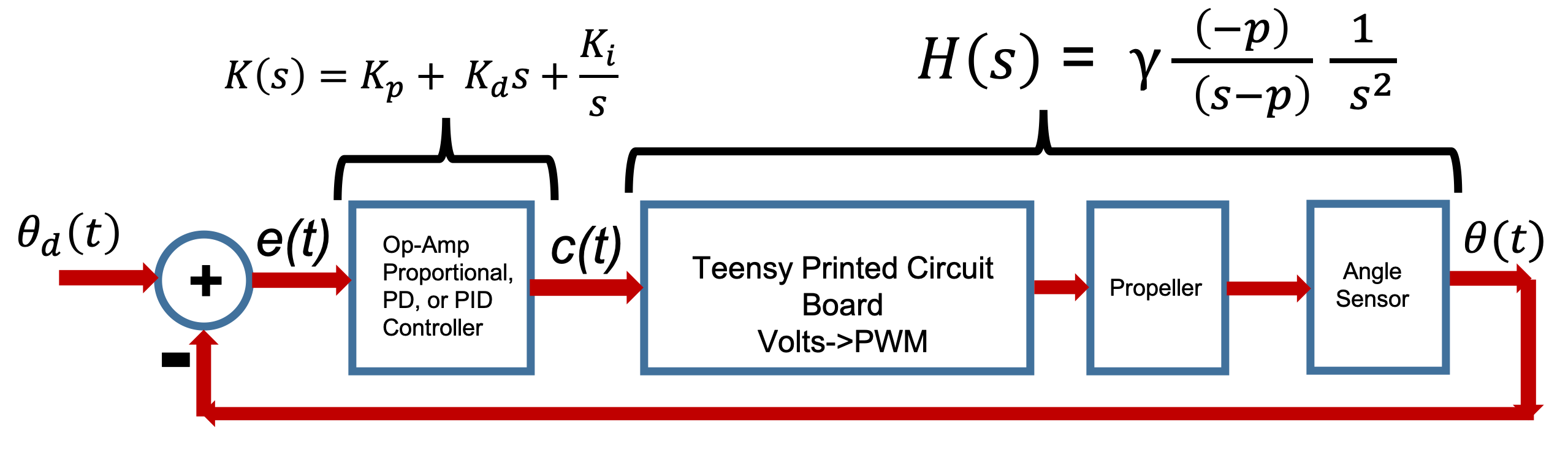
In today's lab, you will be building and testing a CT controller for the nearly CT propeller arm, to gain some insight into the difference between DT and CT control, but also to gain some experience with designing op-amp controllers in preparation for next week's maglev lab. Note that we say nearly continuous-time propeller arm because you will use the Teensy to sample the output of your op-amp controller at 20Khz, and then convert it to a PWM signal at 120Khz. Since the sample and PWM periods are each less than 50 microseconds, both update far faster than any of the propeller's time constants, so we can treat the system as CT.
A block diagram of today's control system with the transfer functions is given below. You will make the PD controller using an operational amplifier and a few capacitors and resistors, using the circuits we discussed in class yesterday (see this week's scribbles). You should also have a calibrated model of your propeller arm system, based on matching frequency responses last week, and you will need that model to design your controllers.
There are several things that change when moving to CT, but it gives us a chance to review many of the ideas you have seen so far. One of the issues we think is particularly confusing is that we will start using a bipolar drive. That is, we will be able to drive the propeller in both the forward and reverse direction, as we will need bipolar drive for Maglev next week. We will also have you learn to use an oscilloscope to monitor signals. To help you untangle these issues one at a time, we will suggest a staged approach to this week's lab.
For Checkoff One:
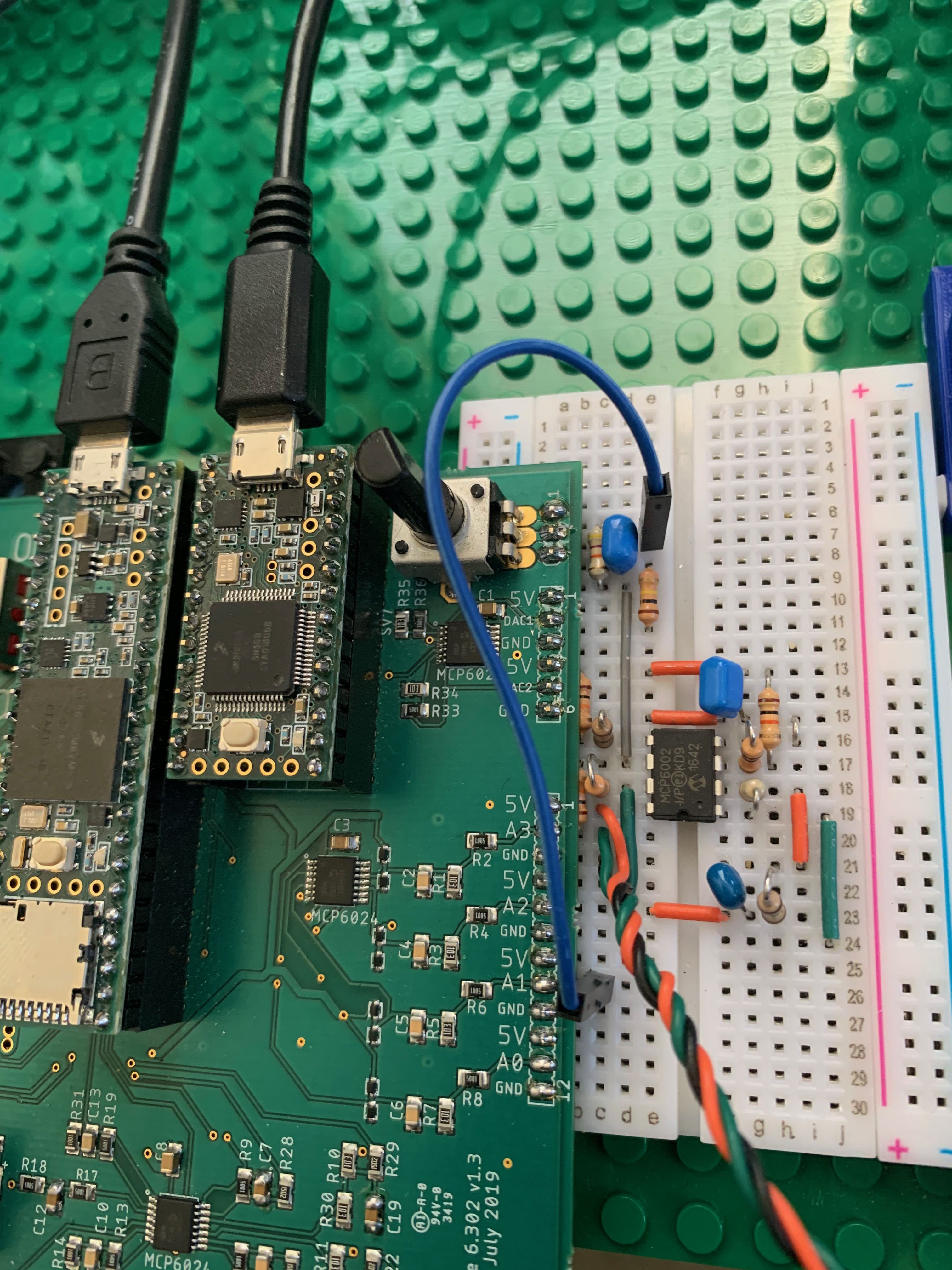
- Get one of the smaller breadboards, wire the circuit below, and connect the breadboard to the PCB.
- Download today's voltage to PWM sketch (above), set cmdNominal to zero, and flash it on to the Teensy.
- Remove the yellow jumper, connect the PCB potentiometer to A1 analog input, connect up your laptops to the Teensy's, connect and turn on the power, and make sure you can drive the propeller in either direction by turning the potentiometer (with the center of the pot being zero current to the propeller).
- Use the pocket oscilloscope to monitor the PWM output to the propeller as you adjust the potentiometer. Be prepared to explain what you see.
- Remove the jumper connecting the potentiometer to the A1 input, replace the yellow jumper, and, WITHOUT the capacitor, set the resistor for a proportional gain of one.
- Using the monitor (which shows you the motor command and the error from the op-amp summer), calibrate the cmdNominal and angle sensor offset so that the error is zero when the arm is horizontal and the potentiometer is at its middle setting (you can feel the potentiometer "lock in" when you are at its midpoint).
- By holding the propeller arm and moving it above and below the desired angle, be sure that the propeller responds correctly (it blows more air down when you are below the desired angle, and less when you are above the desired angle).
- By holding the propeller arm and moving it above and below the desired angle, be sure that the propeller responds correctly (it blows more air down when you are below the desired angle, and less when you are above the desired angle).
- Use the oscilloscope to monitor the A1 signal (the command output from the second op-amp). You will find it easier to make measurements if you create a 2.5 volt reference (using two 10k resistors, a 47ufd capacitor, and a single yellow jumper) for the black scope lead.
For Checkoff Two:
- Determine resistor and capacitor values for a good PD controller using your matlab model for your propeller, a matlab model for the controller, and the matlab command 'step(feedback(Ks*Hs, 1))' which should be familiar to you now.
- What happens when you try to using large values of the derivative?
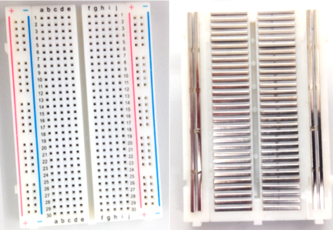
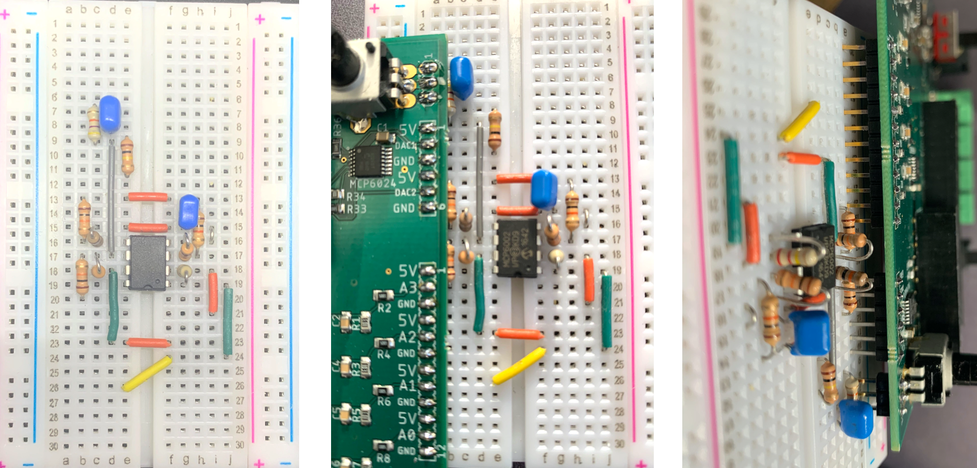
If you have not seen a solderless breadboard before, below is a picture of the front and back of the board, showing how the holes are "connected".
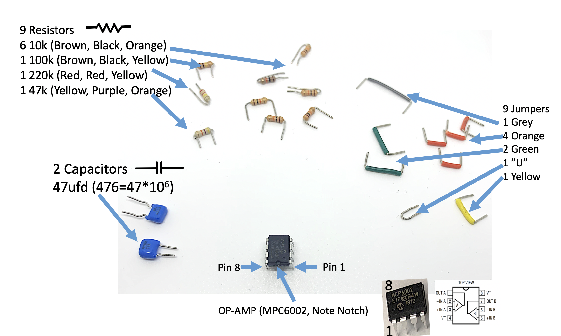
Along with a smaller breadboard, you will need one MPC6002 operational amplifier, blue capacitors, color-coded resistors, and precut jumper wires (green, orange and yellow). All the parts can be found in trays on the white table in lab. The 10k \Omega resistors are brown-black-orange, and 220k \Omega resistors are red-red-yellow, but 1k \Omega resistors are brown-black-red, so WATCH FOR RED ORANGE ERRORS! It can be confusing when your resistors are different from what you thought by an order of magnitude.
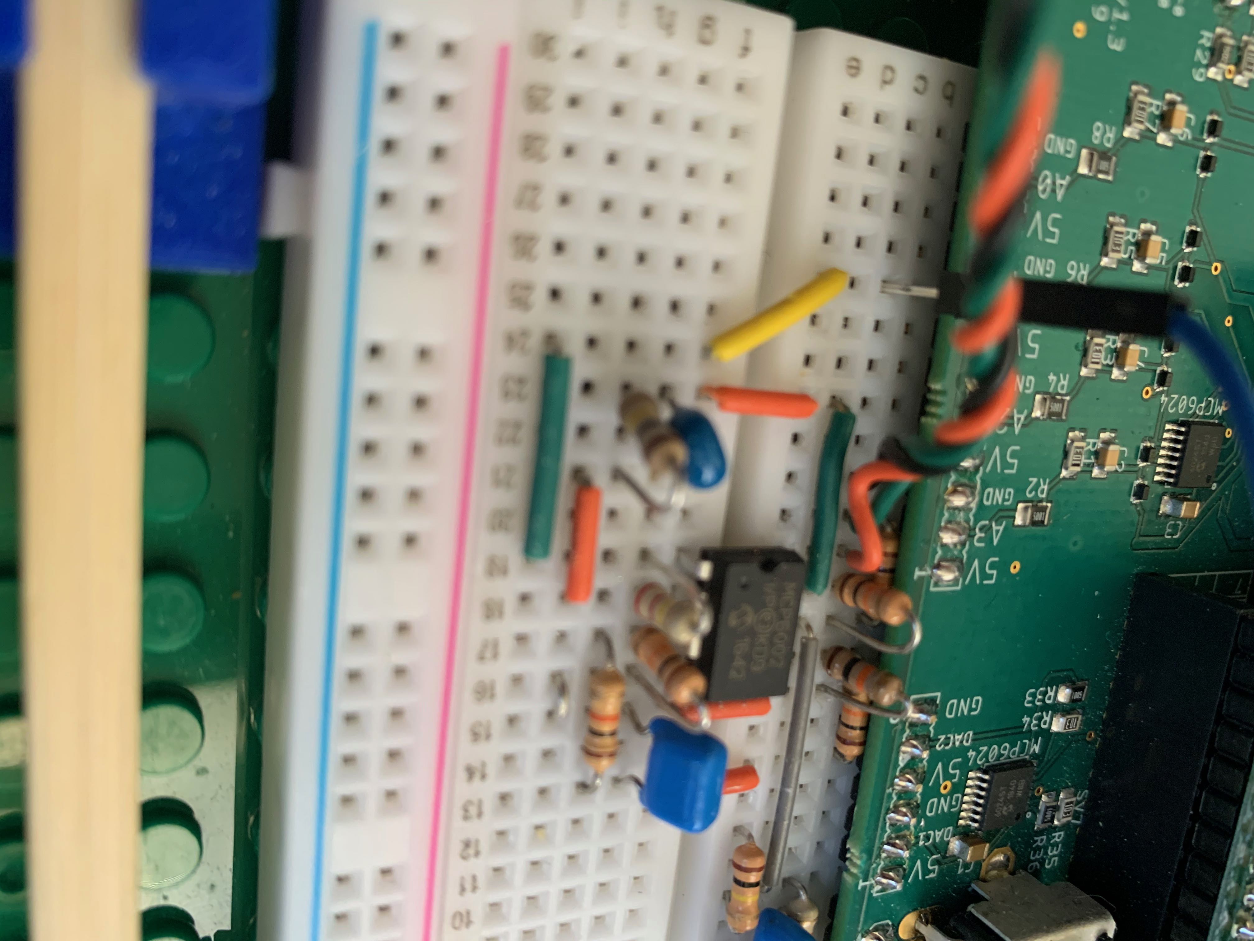
The circuit schematic and board layout are shown below.
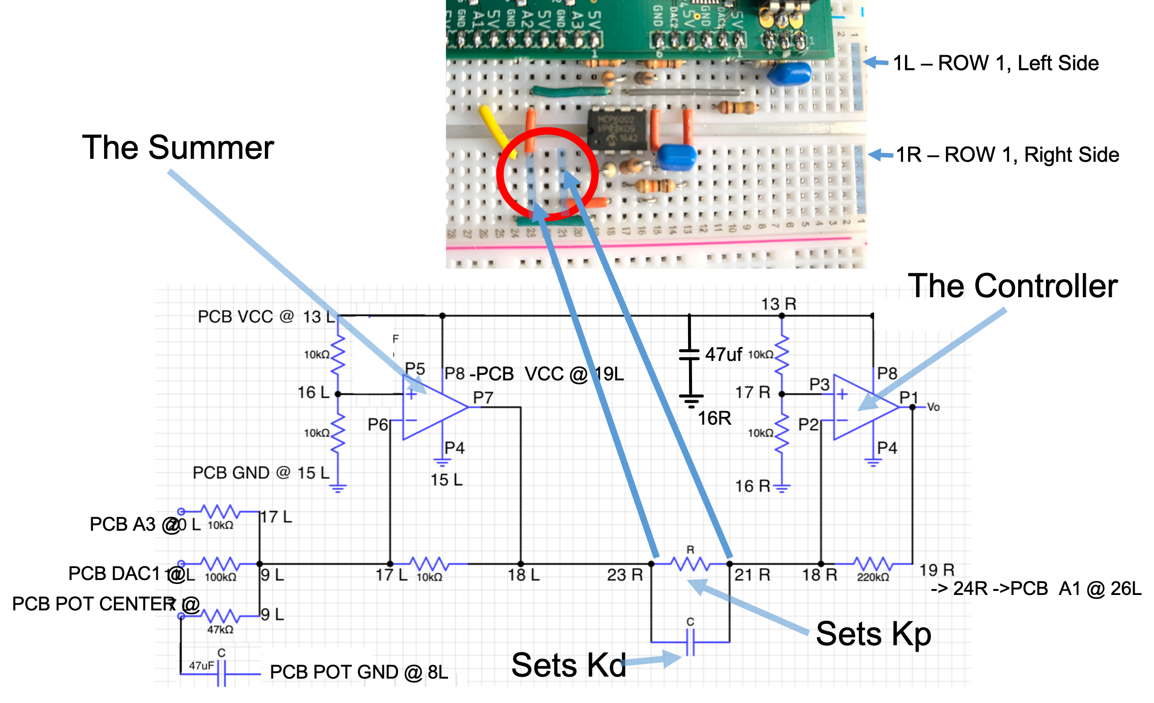
Alternative views of the board layout and connections the the printed circuit board are shown below.
BORROW one of the oscilloscopes connected to a charger (but please replace it at the end of lab!!!), and connect it to monitor the PWM signal from the board, as shown below.
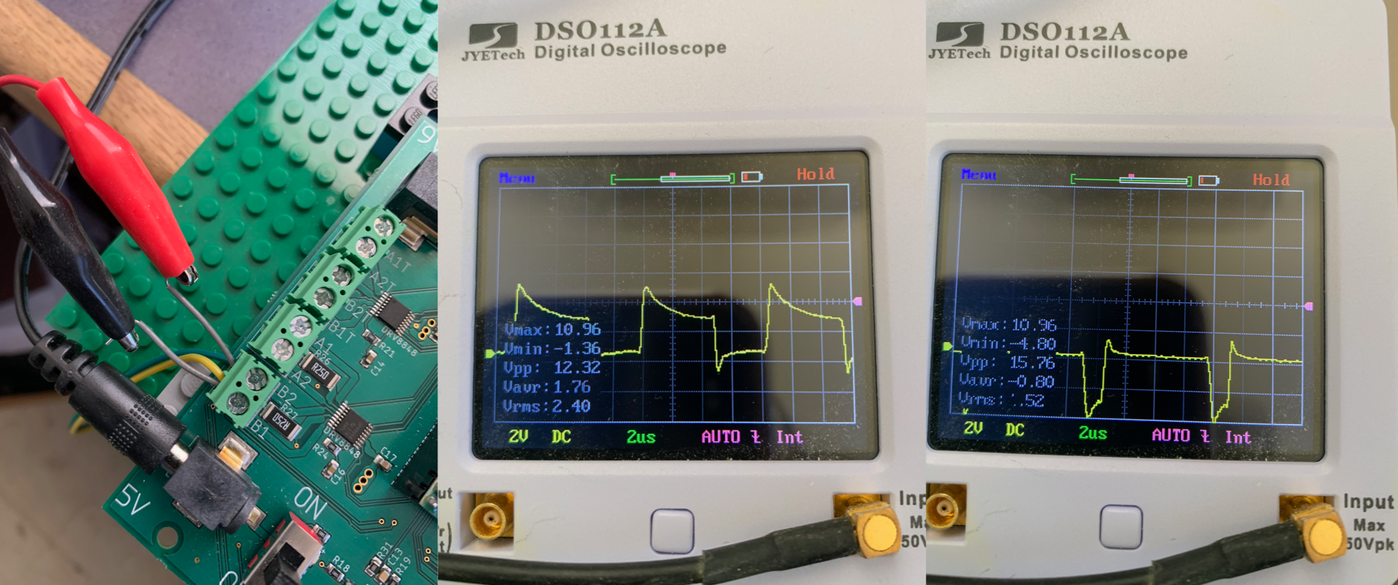
Use the PCB potentiometer to generate a signal from 0 to 5 volts, and since you jumpered it to be the input to the Teensy-based V2PWM converter, you should be able to adjust the potentiometer t spin the propeller in either direction. Carefully, the propeller will pop-up when you transition from blowing air up to blowing air down.
Once you have verified that you can drive the propeller in either direction, remove the pin-jumper and replace the yellow jumper wire. Then etermine a value for R in the schematic to set up a proportional controller with a gain of one, and add it to your circuit.
Once you have a gain of one proportional controller, set the analogOutSquareWaveAmplitude to zero, and calibrate the cmdNominal and angleSensorOffset values in the Teensy sketch so that the arm "stays" roughly level with zero error. Does your propeller respond appropriately as you force the arm too high or too low? MAKE SURE YOU HAVE THE SIGNS RIGHT!!
What does your matlab model predict about the behavior of the proportional-only controlled CT arm? In Matlab: FORM Ks and Hs and then use the step(feedback(Ks*Hs,1)) command! DO NOT USE THE CLOSED LOOP TRANSFER FUNCTION FROM LAST LAB (but you should use your p and gamma values)!!

What next? Using analysis, matlab, trial and error, pick R and C to get a good PD controller (you can even grab an extra capacitor or two and use series or parallel to make other cap values). Be sure the use OUR BLUE NONPOLAR Capacitors!!!
While you are designing the controller, have a look at the controller's frequency response and think about the non-ideal model of an op-amp.
When you think you have a good controller, you will want to examine the system's step response. You can add a square wave input by setting analogOutSquareWaveAmplitude to a non-zero value (like 0.25 or 0.5). You can alter the square wave's amplitude and period by altering its parameters at the top of today's Teensy sketch and then reflashing.
With the square wave added in, you can generate step responses from your new CT controlled propeller. Test out your controller and see if you measurements match matlab. Try using a very big value of K_d (using one or two 47ufd capacitors), what happens? What value of K_p can you use according to the matlab model? If you have an okay controller but your motor sounds really noisy or rough, get on the queue and ask for help. We have a little trick to show you.
We will examine a more realistic model for the op-amp in the postlab.